Mapping Module Validation
After arduous work in programming and design a basic slam implementation has been completed. Much work remains to implement and validate the system so that it works and will perform optimally. This blog post describes the beginnings of an approach to slam validation.
ROS simulators and comparisons
As the final product will be deployed on a system that runs ROS I will utilise ROS as the testing environment. The gif below simulates a basic world with a number of cones and a dummy racecar that drives around at random and detects cones with some error. This measurement is then passed along to the actual slam algorithm which is then outputs a pose.
This simulation is very basic and has a number of noted limitations. It will work for basic validation but not for a more sophisticated verification of the slam modules performance. Especially given that the forward kinematics model and that the inverse sensor model are very naive. Fortunately the open source community provides a number of useful tools. One source that I have drawn on was sourced from the preeminant team at AMZ racing (ETH Zurich’s team): Souce code here
Unfortunately, this simulation is designed to interface with the AMZ autonomous stack so another layer of interfacing is necessary to make this all work in ROS. The simulation released by AMZ publishes point cloud data where the slam algorithm recieves messages of the type shown here. A simple intermediary python script resolves this; taking in ros pointcloud2 type messages and outputting the custom MUR message to be ingested by slam. We can see all of this happening in the following ros graph. The simulation contains a number of complex nodes that are unused, the useful slam related stuff is in the top right.
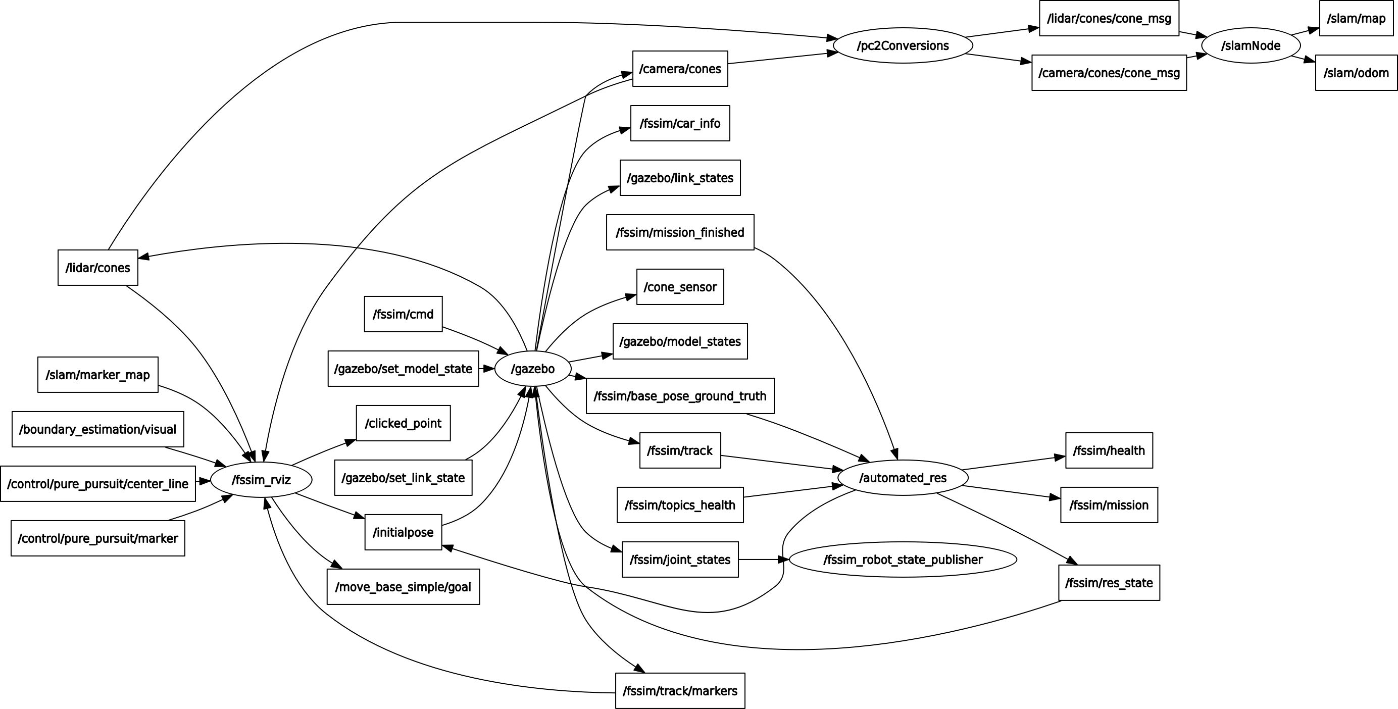
As we can see this is quite a complex simulation, as such going forward the first step will be to validate with the basic simulation aforementioned. The more detailed simulation makes a number of improvements over the basic python script, beyond being merely better from an aesthetic standpoint.
- The detailed ROS simulation uses a complex forward kinematics model that makes it significantly more computationally complex, however the vehicle dynamcs and therefore sensor readings will be more likely to reflect the real experience of the vehicle.
- However, the associated downside is that the simulation is slow, often running at only 75% of real time on my computer. This makes the workflow signifincantly more cumbersome.
- The smaller more lightweight validation tool is much more easily configurable. Runs in a very lightweight fashion and can be easily changed “on the fly”. Meaning that I can spend more time developing slam and less time developing the simulation to test slam. Which is auxillary to my actual aims.
Summarising these points a pretty clear workflow and validation process becomes clear.
- Use the lightweight simulator to do early stage debugging and editing of the slam algorithm. Achieve basic acceptble performance in this simulator by iteratively improving ekfslam through continued testing.
- Having acheived some basic functionality as a mapping algorithm, use the more detailed and powerful simulation to verify the mapping accuracy in a way that mimicks the real world more accurately.
Longer term a more robust and detailed performance valdiation of the slam algorithm can then be verified by taking the inverse steps and revisualizing the estimated cones position against the ground truth. As we can see the power of ROS is that changing out nodes make it easy to switch between simulated testing and the actual deployment of the slam module. However there is much more work still to do before this will work on hardware.